| LispmFPGA |

| LispmFPGA |
 Home
Project Log
The code
Videos
Sample
Home
Project Log
The code
Videos
Sample
10/05/08
The day before yesterday I wrote a faster pair of serial transmission/reception programs to transfer SRAM contents to the FPGA card. Now can transfer 130KByte in about two minutes, by using larger transfer blocks.
Having the faster transfer programs at hand I proceeded to getting the editor run on the FPGA hardware. Everything seems to work now correctly, after I eliminated an obvious bug in windows-02.lisp: The function (main-dispatch) called correctly with zero arguments was erroneously declared with one argument, leading to totally unforeseeable results.
There still seem to be some problems with the garbage collector, which sometimes works ok and sometimes crashes, but I have no time to elaborate on that.
Night to the 1st of May, 2008.
During the last month worked almost every day on the project. Now a hardware design is completed, that runs stable at 12.5 MHz. A little Lisp-E01 program allows transfer of data to the FPGA SRAM. This is intended for transferring executables to the SRAM and running them out of SRAM. The implementation of this feature exhibited a severe error in the SRAM controller caused by misleading Verilog code that worked only in simulation. Also the reset logic of the FPGA system had to be seriously improved - there was no stable startup of the CPU before, a circumstance I wrongly ascribed to timing problems.On the software side I wrote a little text-editor in Common Lisp, but using only a subset that the Lisp-E01 compiler can translate. After testing it as a Common Lisp program I intended to transfer it first to simemu, then to the real FPGA system. Transfer to simemu was possible after some rewrite and debugging, but all attempts to get the program run on the FPGA failed. So I tried a simpler version, which worked partly after correcting some more or less obvious errors, but exhibited unexpected failure in the keyboard driver.
To analyze this I went back to the simemu, who suddenly also produced errors related to the keyboard driver. But here it turned out, that an error in simemu (STO and some other opcodes wrongly implemented) was the cause. The compiler and the keyboard driver itself were ok.
So I got the editor finally running the day before yesterday. Now it was time for the final test: Trying to get the garbage-collector run together with the editor. Yesterday I wrote a little setup, allowing to request a garbage-collect on pressing key F1. As expected, everything crashed, but this night I seem to have weeded out at least those errors that could be found by inspecting the code and thinking about it. Now the editor runs more or less indefinitely and shows no visible errors after some small number of explicitly requested garbage-collections. Only sometimes there is still suddenly a crash. This looks like a tough debugging problem, but I will put it aside to somewhere in the future. The only thing that I will still try is getting the current state of the editor-software running also on the FPGA hardware.
After this I will take a break with the project, as other obligations are approaching me. If someone is willing to take the project at this stage and go further with it, I will be most happy to provide the necessary informations for getting things running.
19/03/08
Completed the simemu simulator/emulator program. Can now try out all code with simemu before loading and running it on the LispmFPGA hardware.
17/03/08
Hardware is now (more or less) complete. At last integrated RS232 receiver and transmitter. Also complete interrupt capability tested and working, can read keyboard codes from PS/2 keyboard, read and send characters from and to serial port (tested with hyperterminal). Also I understand now how to use a tool (data2mem) that allows to change in the .bit-file selectively the contents of the BRAMs. So there is no need anymore to go through the whole synthesize-map-place-route cycle to load a new test program to the card.
Also some minor restructuring done to save logic elements. Removed the hardwired 7-segment LED-Block control, changed to a processor soft-controlled version. Also added provisions to halt the processor and selectively disable interrupts through the user switches on the Spartan card. Also configuration of bank select logic done by user switch (decides if startup from SRAM or Spartan internal BRAM).
Finally started to program a full instruction level simulator of the card, inclusive keyboard interface and VGA Output. Called this program simemu, current version available on the code page. At the moment it can simulate everything except for VGA memory accesses and interrupt processing. But this should not be too difficult any more. By the way, simemu was done with the Qt toolkit, that I like very much in general, but in this case there where really some unnecessary technical obstacles (in assigning colors) to overcome.
Not to forget at last: Had to correct a bug in the compiler (in phase 1, comp-1.lisp) that managed to slip through what I thought was a quite extensive testing.
01/03/08
Many successes. Last two weeks implemented new clean bus structure in main.v. Now have banks A, B, C, D for bus slaves, only CPU is bus master. A is FPGA internal RAM, B is VGA RAM, C is SRAM and D is for memory mapped devices. Currently a device is connected, that resets the CPU when addressed and if specified does a switch of the select addresses for the banks.
These are by default
A 0xyzuvwr
B Fxyzuvwr
C Dxyzuvwr
D Exyzuvwr
Bank selects A and C are switchable to move SRAM memory from Dxyzuvwr to 0xyzuvwr.
Also the processor has working basic interrupt capability. This was achieved by very modest changes to the processor code, adding one bit in the microcode row and writing three new microcode routines. Two simple ones that deal with a newly added status register and a somewhat more intricate that simulates a closure call CALLCLOS 1 to an interrupt service routine. Such a routine is simply an ordinary Lisp funtion fulfilling certain restrictions with its pointer entered into the IRQ vector table (currently just one location).
All this was successfully tested on the simulator by extending the testbench with logic that generates an interrupt on keypress in the Qt output window. As preparation for the next step I finally wrote a PS/2 serializer module in the testbench. This module sends the keypresses delivered through VPI functions to the model simulated by Icarus Verilog simulator as correctly PS/2 encoded data to the already established PS/2 decoder, which will later of course be part of the final hardware.
18/02/08
Moved the current design from the ISEProject (Proto200) over to the simulation environment (micasm). Did some necessary modifications, because with Icarus the Xilinx Library Standard parts can not be used and therefore equivalents have to be provided. Also a model for the ISSI SRAMS on the board had to be provided (easy, as I did not strictly adhere to timing and functionality).
Nevertheless an oversight in the coding of the SRAM-controller state machine became apparent that did not show up on the hardware - there seems to be simply no replacement for simulation. After correcting this mistake everything worked fine.
But even before the SRAM-controller mistake something really ugly happened: The simulated CPU did not start. After circles of debugging, the reason finally found was a "wrong" value for the length of the reset pulse - it had to be carefully aligned to the CPU clock. Probably I should give this problem some thoughts before the hardware is "released", although on the hardware there was never a startup problem.
Plan for the next days: Finally start building a proper keyboard interface. The problem here is, that so many possible solutions come to mind - it's difficult to choose. In any case a mechanism for interrupts has to designed.
17/02/08
Redesigned the webpage for LispmFPGA. Also decided during the last days to build an SD/MMC card interface to the Spartan card. In this way an SD/MMC card can be used for initializing the SRAM and as permanent memory. Interface logic will be SPI logic with mostly software generated timing.
14/02/08
During the last days I build an SRAM control logic (a small state machine) and an interface of this logic to the CPU. Big complication first were two different clocks (clk_sram, fast, and clk_cpu, division of clk_sram, both generated by a DCM). The state machine for SRAM control had to synchronize on both. Finally I found only one way to get it working: Derive clk_cpu from the state machine itself.
An aside about the state machine: Yesterday night, when the system did its first successful reads and writes to SRAM, it was a Moore-Machine with unregistered output. After reading about glitches and rereading MITs Open Course Ware 6.111 I changed it into a Mealy-Machine with registered output. Now it works at 60ns cycle time for processor and sram with 20ns included for sram access. Maybe I can push this down even a bit more.
To Do
Create with VPI-Routines a working Input/Output model of the Lispm-FPGA. The model runs under
Linux. On simulation start, an output window opens, on which the Lispm-FPGA writes characters like
on a terminal. The hardware version currently uses a 6x11 font on a 800x600 screen,
the software version will mimic that. So we use maximal a 133x54 display (with 8K VideoRam being sufficient).
First Step (Linux Simu): Create a working video RAM interface in the file cpu_tb.v in addition to
the main RAM already in place. Basic structure for this done, by now (22.01.08) debugging.
Second Step (Linux Simu): Write a VPI-program that builds and displays the output window
(how?OpenGL?Qt?).
Extend the program with a logic that monitors the VGA-RAM and reflects change in VGA-RAM in the
generated window.
Third step: Think about keyboard input logic. Needs preferably the presence of interrupts in processor.
Most simple interrupt concept: micro-code driven polling for interrupts at start of instruction fetch.
Problems of higher interrupts (exceptions, interrupts in mid of instruction) later.
Fourth step: Think about software principle for using the interrupt logic for keyboard input.
...Possible further elaborations
Milestone1: A self-standing system basis-01.lisp with
running in Linux-Simu
Milestone2: Transfer system from Milestone1 into reality (Spartan 3 Starter Kit).
Hairy complication: Have to learn how to store and retrieve the initializing data into and from the
FPGA configuration RAM. (see Xilix App Notes for Spartan 3 Starter Kit).
Little complication: have to write a SRAM interface logic for the ISSI chips.
19/12/07
Gestern beschlossen: Jetzt will ich die Räder rollen sehen!
...und sie rollten!
09/12/07
Gestern konnte ich eine wichtige Aufgabe erledigen: Die Funktionen
(%make-vector n)
(%make-closure a b)
(%reserve-space n)
die bisher als Prozessorinstruktionen mit eigenem Mikroprogramm implemementiert waren, werden jetzt als Aufrufe ((get-word 200 0) n) bzw. ((get-word 200 4) a b) bzw. ((get-word 200 8) n) abgewickelt.
Das heißt, der Compiler übersetzt in ganz normale Closure-Calls, wobei die Adresse des Closures in Adresse 200 oder 204 gespeichert ist. Beim Erzeugen des Ur-Speicherbildes werden entsprechende Closures aus dem in Lisp geschriebenen Sourcecode für die Funktionen make-vector usw. kompiliert und Verweise auf diese Closures in den Adressen 200, 204 und 208 abgelegt. Die Adresse 224 enthält den Allokationszeiger. Analog könnte man weitere feste Adressen außerhalb des Heap- und Stackbereichs als globale Variable für systemnahe Funktionen vorsehen.
24/11/07
In den letzten Tagen habe ich den Entwurf für den E-Prozessor stark überarbeitet. Dabei erwies sich die "generische Stackmaschine" aus dem Buch Stack-Computers: The New Wave von Philip Koopman als gute Ausgangsbasis und auch als Augenöffner für die Lösung von allerlei Designproblemen. Vor allem ein TOS Register für den Datenstack und das Mikrocode-Format habe ich gern übernommen.
Der Aufbau eines Mikroprogrammwerks und seine Verzahnung mit den Designelementen der CPU ist hier sehr gut erkärt. Also begann ich vor etwa einer Woche endlich mit dem Schreiben eines Mikroassemblers - ein Schritt, der durch den LL(1)-Parser-Generator, den ich Mitte 2007 geschrieben hatte, sehr erleichtert wurde. Nur den Lexer mußte ich selbst schreiben, wie üblich eine etwas unangenehme Sache.
Als der Mikroassembler dann vor drei Tagen fertig war, nahm ich mir für die darauffolgenden Tage die Implementierung des Mikrocodes für einen Teil des gesamten geplanten Befehlssatzes vor, speziell für die Befehle, die in einem kompilierten Fibonacci-Programm auftauchen. (Programm *tsta1* in comp-test.lisp aus meinem mevalxp-Directory).
Daneben mußte ich noch ein bißchen über Testbench-Gestaltung in Verilog lernen, wofür sich Deepak Kumar Talas asic-world.com als sehr nützlich erwies. Es war noch ein bißchen Verbindungscode zu schreiben, um den simulierten Speicher aus meiner Lisp-Simulation des E-Prozessors (der dort EMU heißt) als Verilog gerechten Hex-Dump ausgeben zu können. Solche Dumps auszugeben mußte auch der Mikroassembler können, also war es nichts neues.
Überhaupt hatte ich mich schon vorige Woche - was sich als goldrichtige Entscheidung erwies - für eine echte Verilog-Simulation meines E-Prozessors, wie er eben als Verilog-Source gegeben war, entschieden. Die zuerst verfolgte Idee, den Mikrocode mit einem selbstgeschriebenen Lisp-Programm zu interpretieren wäre wohl ein Unsinn erster Güte geworden. Nicht nur hätte man eine Quelle überflüssiger Arbeit und unnötiger Bugs, außerdem wären die Umarbeitungen am Prozessor immer doppelt zu machen gewesen: Einmal in der Verilog-Quelle und dann nochmal im Mikrocode-Simulator.
Danke also, daß es den Icarus Verilog Simulator gibt und ich so alle schwierigen und langwierigen Tests in meiner hochgeschätzten Linux Umgebung machen kann. Daß Icarus von selbst ein eher Text-basiertes Werkzeug ist, stört beim Prozessor-Debugging überhaupt nicht, im Gegenteil: Die geordneten Zahlenkolonnen im Output lassen sich hier sinnvoller interpretieren als Liniendiagramme von Logikpegeln.
Seit zwei Tagen bin ich also am Schreiben des Mikrocodes, gestern war alles für einen Fibonacci-Test fertig. Wie erwartet und befürchtet: Der erste Start brachte noch keinen Erfolg, und das obwohl ich die meisten Befehle nach der Implementation sorgfältig einzeln getestet hatte.
Wer also war der Schuldige? Waren es die langen Mikrocode-Sequenzen in denen auch Heap-Speicher alloziiert wurde? Oder ist bei LOD d oder STO d oder CALLCLOS d etwas schiefgelaufen. Es sind zwar nur wenige Befehle, aber beim direkten Programmieren am Schirm vertut man sich hier leicht, wenn man die Idee nicht vorher auf einem Blatt Papier mit der Hand skizziert hat.
Kurzum: Es gab mehrere Schuldige, auch einige unschuldig Verdächtige und ganz am Ende war es ausgerechnet der unschuldige JNIL d Befehl der so grob falsch kodiert war, daß ich es selbst kaum fassen konnte.
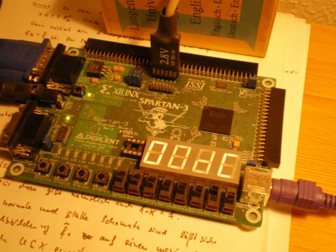
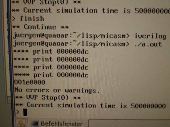
Heute nacht, etwa gegen Mitternacht von Freitag auf Samstag war es dann soweit: Fibonacci(9) wurde richtig berechnet und der Verilog-Simulator zeigte den erwarteten Wert (000000DC) an. Das ist 220 dezimal und richtig, weil meine Lisp-Implementation zwei Tag-Bits rechts vorsieht. Ich gebe zu: Es war ein Moment, in dem man mit ein bißchen Selbstbewunderung innehält.
31/01/07
Es ist geschafft: Ein run-time System ist geschrieben, das den Speicher der Lispm-FPGA als array abbildet. Darin werden alle für ein Lisp-System grundlegenden Lisp-Datenstrukturen abgebildet, also
sowie zwei Strukturen, die für das Handling von closures und code-Vektoren nötig sind
Außerdem fertig: Ein einfacher Simulator des Zielprozessors (eine Stackmaschine mit Datenstack und Adressstack). Der Simulator arbeitet auf Instruktionsebene (also nicht auf der Ebene eines derzeit noch hypothetischen Mikrocodes).
Und schließlich: Ein großer Teil des Codegenerators des Compilers, der Assemblercode für den E-Prozessor erzeugt (so nenne ich einfach mal meinen Stack-Prozessor), läuft.
Zu guter Letzt, ebenfalls fertig - wie sich zeigte eigentlich trivial - die letzte Stufe des Compilers: ein einfacher 2-Pass Assembler, der auch gleich als Linker und Loader fungiert. Keine Hexerei: einfach nur geschickte Ausnutzung der Funktionen aus dem oben erwähnten run-time Modul.
Everything can now be found in the new mevalxp directory
20/01/07
Closure conversion now fully implemented in comp-xp-03.lisp. Now it's time to start implementing code generation - phase 4 in the comp-xp-03.lisp program.
06/01/07
Now working on the compiler. Worked on the small module to do free variable analysis on lisp code with nested lambda, labels and setq.
Also collected a lot of information about compiling Lisp. Links can be found in my bookmarks (at Root: Projekte: LispMachineFPGA)
04/01/07
A small aside: Also pondered about moving everything over to Scheme instead of Lisp, but after porting the meval program to Scheme finally decided to stay with Lisp. Reasons:
30/12/06
Added macros to the interpreter. It now has defun, do, defmacro, setq and some other special forms, which allow to write the Lisp-X0 interpreter in Lisp-X0 itself.
But nevertheless the compiler is much more important. The meval-directory mentioned above contains a preliminary sketch for scope analysis of variables in this compiler.
12/12/2006
The method described below to get an interpreter for Lisp-X1 as a E0 program running on an FPGA becomes a bit superfluous as I now understand the process of compiling closures a little better. Playing with CLISP and disassemble gave me some hints how to use full closures and keep a (mostly) stack (vs. heap) regime for the environments notwithstanding.
The interpreter Lisp-X0 has now grown quite a bit and a reader for Lisp-expressions has been added to the file containing it.
It can be found in
the meval directory as
meval-pack.lisp
with defpackage-file meval-pack-i.lisp to be read in before.
My goal is now to write a compiler for full Lisp-X1 in Lisp-X1 itself. Especially it should provide full support for closures.
02/12/2006
Corrected error in implementation of FUNARG
01/12/2006
The program at the "Lisp in Lisp page" is the sketch of an interpreter, that I call Lisp-X0 in the following. Lisp-X0 is a "downward circular" interpreter for a Lisp dialect essentially defined by that interpreter itself. This dialect has lexical scope and follows in semantics Common Lisp use. It shall be called Lisp-X1.
The phrase "downward circular" is to be understood as follows:
To execute Lisp-X0 it is possible to regard it as a subset of Common Lisp. But the goal is to have a compiler (comp-0) translating Lisp-X0 into an intermediate language (called X0), which will then be mapped to a concrete, real processor (E0)
At first a E0 emulator in Common Lisp has to be written, but later the processor E0 will be implemented on an FPGA.
Consequently at this stage Lisp-X1 will be provided on that FPGA, but only in an interpreted way.